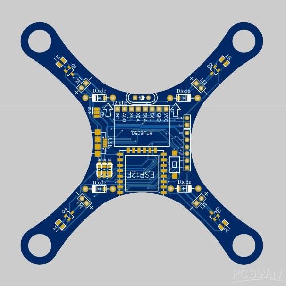
PCBs are the electrical signal transmitters that provide electrical connections to their attached devices. The PCB manufacturers design them in different shapes to facilitate the users accordingly. The manufacturers design, create and fabricate the PCB to provide users an optimum performance. This article will discuss the process of manufacturing one of the strange PCB shapes. Drone PCB manufacturing requires the operation of the software that we explicitly discuss in the following steps:
Design drone shape with AutoCAD software
The PCB creation for a drone requires the manufacturers to draw the basic design of the drone. The AutoCAD designing software generally helps here. Draw the drone structure by choosing shapes: circle and line from the address bar of the software page. Draw the structure according to your desired size. You can go for 40mm, 55mm, and 65 mm drones. Yet, the 55mm drone size is preferable as it can accommodate nearly 8520 motors. Ensure that the edges of the lines are curved to extend the durability. Surround the structure with a square box after drawing the basic drone shape. Save the final document in dxf format.
Create circuit design with EASYEDA software
Once the shape design is complete, design the PCB circuit with EASYEDA software. Plan a new PCB project and create its symbolic portrayal to show its working step by step. You can use the netport for drawing a clear and simplified symbolic diagram. Then, convert your layout to the PCB by clicking on the structure after giving it a finishing touch. You can also verify your design by rechecking for any flaws or errors by employing design rule checking (DRC) on the circuit board.
Share the Drone PCB design to EASYEDA
Transfer the drone diagram on dxf format from AutoCAD to EASYEDA. You can do this by clicking on the file option, selecting import from the dropdown, clicking on DXF, choose the required file from the list to share the AutoCAD file. While doing this, ensure that you have set the unit to mm and the board outline layer with a stroke width of 0.254mm. Tick the box marking convert circle to hole to drill the hole for placing motor mount.
Manual Routing or through AutoRouter
It’s time to route the signal traces after fixing the motors on the PCB drone design. The manufacturers can do it through AutoRouter and manually. Manual routing is generally preferable. Set the power line width for the motor to at least 0.4 to 1 mm because it operates on nearly 2A current, which can result in burning the power line due to a short circuit if the power line width is only 0.25mm.
Convert the final draft into a Gerber file
After the routing, you can view your PCB for the drone in 2D or 3D to have a comprehensive picture of it. It is significant to add the terminal markings to ensure that the PCB connection isn’t at reverse polarity. After getting satisfied with the final draft, transfer it to the Gerber file, which is the PCB fabrication file. Agree to the DRC check to have a final inspection of the PCB to ensure no vulnerabilities.
Set the PCB width
The final step calls for uploading the Gerber file of PCB to the PCBWay by selecting the required width and weight for your PCB. Ensuring recommended thickness is crucial to avoid excessive PCB drone crashes during its rigorous testing.
Conclusion:
This article outlines the necessary steps to manufacture PCBs for the drone. Following these steps considerably can enable you to ensure Drone PCB with optimum performance and qualitative functioning.
After designing the PCB, you may need low volume PCB service testing, you can refer to this PCBA service.


